The Role of Surface Roughness in Threaded Component Reliability
When Threads Fail, It’s Rarely the Material
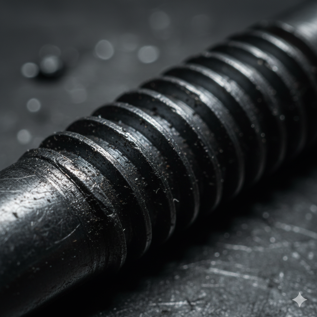
In mechanical assemblies, failure often begins not with the metal’s strength but with its surface condition. Even when using high-grade alloys or optimized geometries, excessive roughness can cause micro-abrasion, stress concentration, and premature fatigue.
Threaded components—bolts, inserts, anchors, couplers—depend on microscopic contact surfaces for their load-bearing capability. A poorly machined surface changes friction behavior, loosens preload, and allows corrosion to initiate.
That’s why at Jingle, surface roughness isn’t treated as an aesthetic property—it’s an engineering variable that determines how a fastener performs under vibration, torque, and time.
Understanding Surface Roughness and Its Mechanical Impact
Surface roughness refers to the small-scale irregularities left by machining or finishing tools. These micro-peaks and valleys dictate how two surfaces interact under pressure.
| Parameter | Definition | Mechanical Relevance |
|---|---|---|
| Ra (Roughness Average) | Mean height deviation | Determines friction and wear |
| Rz (Mean Peak-to-Valley Height) | Difference between highest and lowest points | Influences fatigue initiation |
| Rt (Total Roughness Height) | Combined surface range | Affects sealing and corrosion |
In threaded components, Ra values between 0.8–1.6 μm often represent the balance between manufacturability and mechanical performance.
Finer finishes (<0.8 μm) improve sealing and reduce stress concentration, while coarser finishes (>3.2 μm) increase friction and risk galling.
How Roughness Affects Thread Performance
Surface finish directly influences how torque converts to preload—the true measure of joint integrity.
-
Too rough: Threads bind during tightening, leading to galling or stripping.
-
Too smooth: Reduced friction causes under-torque and loss of clamping force.
-
Uneven surface: Concentrates stress at thread roots, triggering micro-cracks and fatigue failure.
In controlled tests, bolts with optimized Ra ~1.2 μm achieved up to 25% higher fatigue life compared to unpolished counterparts.
Jingle’s multi-stage machining and polishing processes maintain this critical roughness range across all threaded geometries—ensuring uniform performance even after coating or heat treatment.
Manufacturing Comparison: Conventional vs. Controlled Finishing
| Process Step | Generic Machining | Jingle Precision Finishing |
|---|---|---|
| Thread Cutting | Single-pass with tool wear variation | Multi-pass adaptive threading |
| Surface Control | Rough cut with no feedback | In-process roughness monitoring |
| Finishing Method | Basic deburring | Precision micro-polishing & chamfering |
| Inspection | Random sample check | Full Ra & Rz metrology via profilometer |
| Resulting Ra (μm) | 2.4–3.6 | 0.8–1.2 consistent |
Through this controlled finishing pipeline, Jingle ensures every thread maintains dimensional precision and optimized frictional performance under real-world load conditions.
Field Applications: Where Surface Quality Defines Reliability
1. High-Vibration Machinery
Smooth, uniform threads reduce micro-slip and fretting corrosion in rotating assemblies such as pumps and compressors.
2. Structural Bolting Systems
Consistent roughness maintains predictable preload during torque-tightening in bridge and building connections.
3. Aerospace and Automotive Fasteners
Fine surface control minimizes fatigue crack initiation, extending the operational life of critical components.
4. Precast Anchors and Inserts
Corrosion-resistant finishes prevent micro-pitting in embedded environments with high alkalinity.
5. Hydraulic and Sealing Assemblies
Precision-machined threads maintain sealing integrity even under fluctuating pressure.
These examples show that surface roughness isn’t cosmetic—it’s the foundation of reliability across every load path.
Technical Recommendations for Engineers and Procurement Teams
| Application Type | Recommended Surface Finish (Ra μm) | Finish Method | Notes |
|---|---|---|---|
| Structural Bolts (Grade 8.8–10.9) | 1.0–1.6 | Controlled threading + zinc plating | Balances torque consistency |
| Precision Inserts | 0.8–1.2 | CNC micro-finishing | For alignment-critical assemblies |
| Corrosion-Prone Environments | ≤1.0 | Polishing + galvanization | Minimizes crevice corrosion |
| High-Speed Machinery | 0.6–0.8 | Lapping & buffing | Reduces vibration fatigue |
| Standard Industrial Hardware | 1.6–3.2 | Conventional machining | Economical for non-critical joints |
Tip: Always consider how coatings (zinc, phosphate, nickel) will slightly increase surface roughness—adjust pre-coating Ra values accordingly.
Frequently Asked Questions
Q1: Can polishing always improve thread reliability?
Not always. Over-polishing can reduce friction too much, affecting torque control. Balance is key.
Q2: What is the best method to measure roughness?
Contact profilometers or optical interferometers provide the most accurate Ra and Rz readings for small threads.
Q3: How does heat treatment affect surface roughness?
Heat can slightly oxidize or warp surface peaks—post-treatment finishing is recommended for critical components.
Q4: Does coating eliminate the need for fine finishing?
No. Coatings enhance corrosion resistance but can’t correct underlying surface irregularities.
From Microns to Mechanical Confidence
Surface roughness may be invisible to the naked eye, but it defines whether a component performs for months or decades. By mastering this microscopic world, Jingle delivers threaded parts that align torque, strength, and stability—ensuring every fastener does its job from the first twist to the last load cycle.
To explore Jingle’s precision machining and surface finishing capabilities, visit our homepage or reach out via our contact page.