How to Specify Precast Concrete Insert Plates with Welded Studs

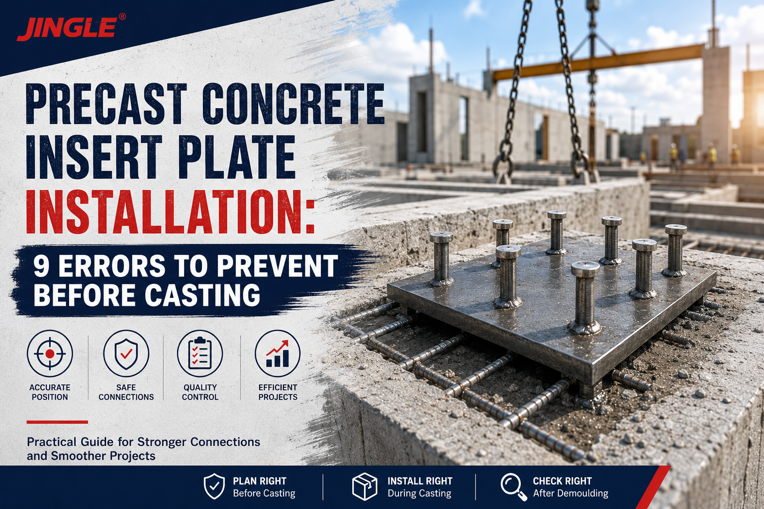
Precast concrete insert plates provide permanent steel connection points inside precast concrete elements. They are commonly used to connect structural steel, façade systems, brackets, machinery supports, handrails, and other secondary components to concrete.
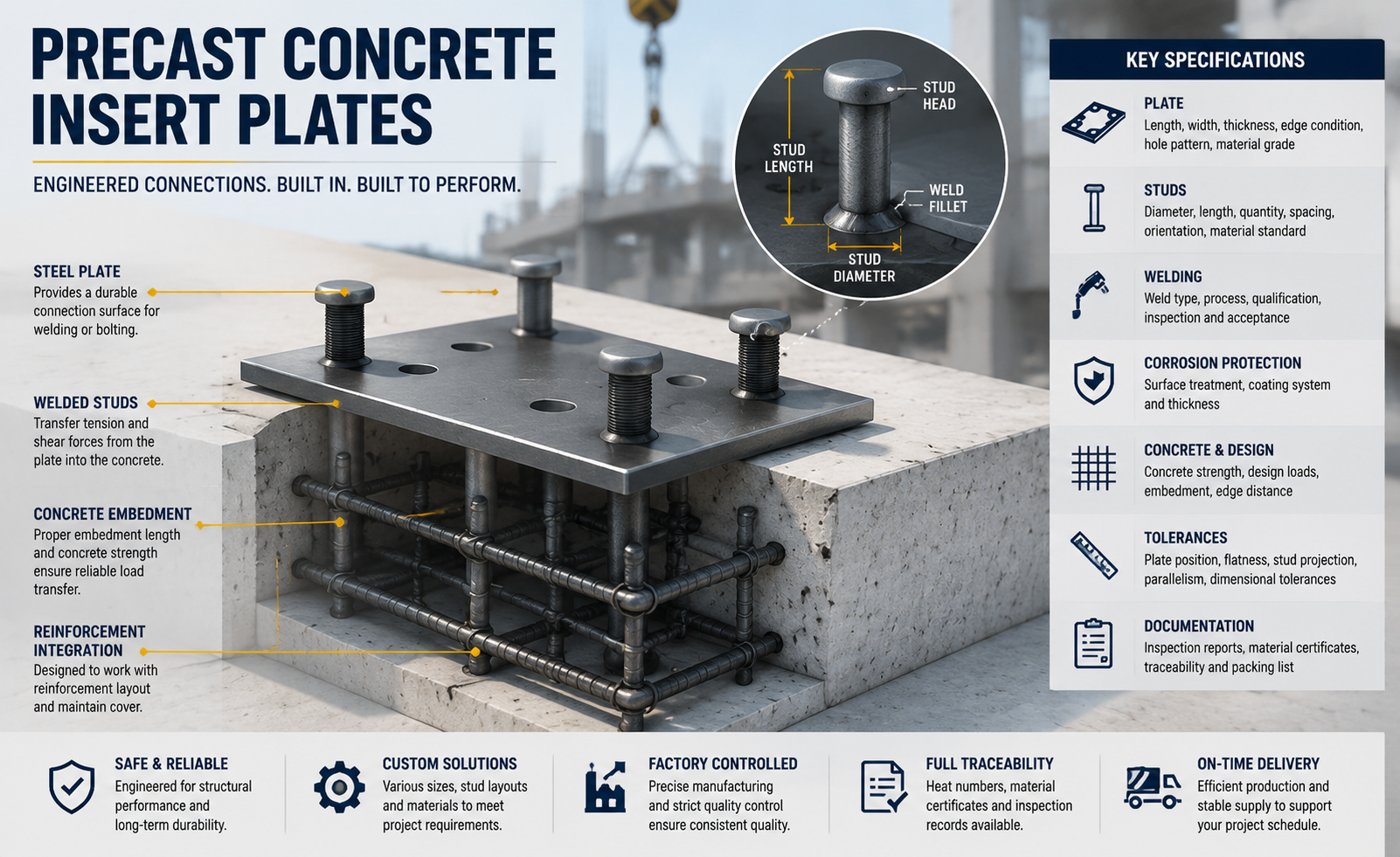
Although the product appears simple—a steel plate with several welded studs—its performance depends on more than plate thickness or stud diameter. The plate, studs, welds, coating, concrete embedment, reinforcement arrangement, and installation tolerances work together as one connection system.
For contractors, precast factories, distributors, and project engineers, a complete purchasing specification reduces quotation errors, production delays, and site modification risks. This guide explains the technical and commercial information that should be confirmed before ordering precast concrete insert plates with welded studs.
Quick Answer
A reliable precast concrete insert plate specification should define:
-
Plate length, width, thickness, and edge condition
-
Steel grade and material standard
-
Stud diameter, length, quantity, spacing, and orientation
-
Weld type and weld quality requirements
-
Surface treatment and coating restrictions
-
Design loads and load directions
-
Concrete strength and embedment conditions
-
Dimensional and position tolerances
-
Inspection and documentation requirements
-
Packaging, traceability, and delivery schedule
Do not select an insert plate using only a product photograph or a general size description. Two plates with similar dimensions may perform very differently when their steel grades, stud layouts, weld procedures, or embedment conditions are different.
1. What Are Precast Concrete Insert Plates?
A precast concrete insert plate is a fabricated steel assembly cast into a concrete element. Its exposed plate surface becomes a connection point after the concrete has cured.
The plate may later be:
-
Welded to structural steel
-
Bolted to a bracket or frame
-
Connected to façade supports
-
Used to secure machinery or equipment
-
Integrated into stairs, balconies, beams, columns, or wall panels
-
Used as part of a temporary or permanent erection connection
The welded studs transfer forces from the steel plate into the surrounding concrete. Depending on the design, these forces may include tension, shear, bending, or a combination of several load directions.
Insert plates belong to the wider family of precast concrete accessories used during the production, handling, erection, connection, and long-term service of precast elements.
Common applications
Typical applications include:
-
Precast wall panel connections
-
Steel beam and column connections
-
Curtain-wall and façade anchorage
-
Balcony and stair connections
-
Equipment support brackets
-
Handrail and safety-barrier connections
-
Industrial concrete structures
-
Infrastructure and bridge components
-
Modular construction systems
The intended application should be stated clearly in the RFQ because it affects material selection, stud arrangement, corrosion protection, testing, and dimensional tolerances.
2. Treat Precast Concrete Insert Plates as One System
The plate and studs should not be evaluated as independent parts. The performance of the complete assembly depends on several interacting components.
Steel plate
The plate distributes the applied load and provides the surface used for the final connection. Its thickness must be sufficient to resist local deformation, bending, and heat effects from welding.
A thicker plate is not automatically the best solution. It may increase cost and weight without resolving weaknesses in the studs, welds, concrete edge distance, or reinforcement arrangement.
Welded studs
The studs transfer forces from the plate into the concrete. Their diameter, length, head geometry, quantity, spacing, and position all affect the behavior of the connection.
A stud that is too short may not provide sufficient embedment. A stud that is too long may conflict with reinforcement or reduce concrete cover on the opposite side of a thin precast element.
Weld connection
The weld is the load-transfer interface between the steel plate and the studs. Even when the plate and studs meet the required material grades, inconsistent welding can create a weak point in the assembly.
Surrounding concrete
Concrete strength, element thickness, edge distance, reinforcement, cracking condition, and installation position influence the final connection capacity. The supplier can manufacture the steel assembly, but the project engineer must evaluate the complete steel-to-concrete load path.
3. Specify Precast Concrete Insert Plates from the Application Backward
A useful specification begins with the connection requirement rather than an existing product size.
Before requesting a quotation, define the following application information:
| Design input | Why it matters |
|---|---|
| Connection type | Determines whether the plate will be welded, bolted, or used with a bracket |
| Load magnitude | Influences plate thickness, stud size, and stud quantity |
| Load direction | Tension, shear, and bending produce different demands |
| Concrete strength | Affects anchorage behavior |
| Concrete element thickness | Limits available stud length and concrete cover |
| Distance from concrete edge | Influences breakout and splitting risks |
| Reinforcement arrangement | May interfere with the stud layout |
| Exposure environment | Determines the required corrosion protection |
| Installation tolerance | Affects plate size, positioning, and connection flexibility |
| Fire or fatigue requirement | May require additional engineering assessment |
If verified design loads are not available, the RFQ should state that the requested dimensions are preliminary and require confirmation by the project engineer.
Load directions
Insert plates may be subjected to:
-
Tension perpendicular to the plate
-
Shear parallel to the plate
-
Combined tension and shear
-
Bending caused by an eccentric bracket
-
Repeated or fatigue loading
-
Temporary erection loads
-
Thermal or shrinkage-induced movement
A plate designed only for direct shear may not be appropriate for an eccentric connection that produces bending and tension in the studs.
4. Define the Plate Material and Surface Finish
The purchasing specification should identify the required material standard or an acceptable equivalent. Avoid descriptions such as “normal steel” or “high-strength steel” without a grade.
Jinglefix’s product information indicates that customized plate dimensions, stud arrangements, materials, and surface treatments can be supplied according to project requirements. Buyers should place the agreed technical details directly on the approved drawing and purchase order.
Plate information to specify
-
Steel grade
-
Applicable material standard
-
Plate length and width
-
Plate thickness
-
Flatness requirement
-
Hole quantity and dimensions, if required
-
Slot dimensions and orientation, if required
-
Corner radius or chamfer
-
Burr removal and edge treatment
-
Marking and traceability requirements
Common surface-treatment options
| Finish | Typical use | Points to confirm |
| Plain or black steel | Indoor or protected applications | Temporary rust protection and storage conditions |
| Zinc-plated finish | Moderate corrosion protection | Coating thickness and post-weld treatment |
| Hot-dip galvanizing | Outdoor or corrosive environments | Venting, distortion, coating thickness, and weld-area coverage |
| Stainless steel | Aggressive or hygiene-sensitive environments | Stainless grade and contamination control |
| Project-specific coating | Special exposure conditions | Compatibility with concrete and field welding |
For hot-dip galvanized components, ISO 1461:2022 provides requirements and test methods for zinc coatings applied to fabricated iron and steel articles.
The coating specification must also identify which surface will remain exposed after casting. If field welding is planned, coating near the weld area may need to be removed and repaired according to the approved procedure.
5. Define the Stud Layout Completely
The stud layout should be communicated using a dimensioned drawing. A written description alone can create uncertainty about spacing, orientation, and reference points.
Specify:
-
Stud type
-
Stud material grade
-
Stud diameter
-
Overall stud length
-
Head diameter and head thickness
-
Quantity per plate
-
Longitudinal spacing
-
Transverse spacing
-
Edge distance from plate boundaries
-
Stud orientation
-
Perpendicularity tolerance
-
Location tolerance
-
Weld position
-
Any interference zones where studs are not permitted
Why stud position matters
Incorrect stud spacing can cause several problems:
-
Collision with reinforcement
-
Insufficient concrete cover
-
Reduced edge distance
-
Difficulty placing and compacting concrete
-
Misalignment with the final connection
-
Local congestion around the insert
-
Changes in the intended load-transfer behavior
For customized assemblies, the approved production drawing should identify a clear datum point so that the supplier and customer measure every position from the same reference.
Account for production tolerances
No welded assembly is perfectly dimensionless. The design should account for practical fabrication tolerances in:
-
Plate length and width
-
Plate flatness
-
Stud center position
-
Stud verticality
-
Overall assembly height
-
Hole and slot position
-
Coating thickness
If the site connection has almost no adjustment capacity, even a technically acceptable insert plate may be difficult to install. Slots, oversized connection plates, shims, or adjustable brackets may be required elsewhere in the system.
6. Establish Weld Quality Requirements
Welding is one of the most important manufacturing controls for precast embedded plates.
A buyer should confirm:
-
Welding method
-
Weld size or stud-welding requirement
-
Weld procedure qualification
-
Welder or operator qualification
-
Base-material compatibility
-
Surface preparation before welding
-
Visual acceptance criteria
-
Production inspection frequency
-
Destructive or bend-test requirements, when applicable
-
Repair-welding procedure
-
Post-weld coating repair
The ISO 3834 series provides a framework for managing quality requirements in fusion welding. For structural steel welding projects based on American requirements, AWS D1.1/D1.1M may also be relevant.
The applicable welding standard must be stated in the project documents. Standards should not be added to a purchase order simply as general references when the design team has not confirmed their applicability.
Typical weld defects to control
-
Incomplete fusion
-
Porosity
-
Cracking
-
Undercut
-
Excessive spatter
-
Stud misalignment
-
Incomplete weld flash
-
Local plate deformation
-
Damage to an existing coating
-
Contamination around the weld area
Visual inspection is useful, but appearance alone does not prove that the weld provides the required mechanical performance. Higher-risk projects may require sample bend tests, macro examination, tensile testing, or other agreed verification methods.
7. Define Inspection and Documentation Requirements
Documentation requirements should be agreed before production. Requesting additional records after the goods have been manufactured can increase costs or create delays.
Depending on the project, the supplier may be asked to provide:
-
Approved fabrication drawing
-
Material certificates
-
Stud material records
-
Welding procedure documents
-
Welder or operator qualification records
-
Dimensional inspection report
-
Weld inspection report
-
Coating thickness report
-
Mechanical test report
-
Sample approval record
-
Production photographs
-
Packing list
-
Batch or heat-number traceability
-
Certificate of conformity
First-article inspection
For a new or customized product, a first-article inspection can confirm:
-
Overall plate dimensions
-
Stud size and position
-
Weld appearance
-
Plate flatness
-
Surface treatment
-
Marking
-
Fit with the customer’s reinforcement or connection components
A physical sample or clearly documented first article can prevent the same error from being repeated across an entire production batch.
8. Compare Suppliers by Total Project Risk
The lowest unit price does not necessarily produce the lowest total project cost.
When comparing suppliers, evaluate the following areas:
| Evaluation area | Questions to ask |
| Technical review | Does the supplier identify missing dimensions or conflicting requirements? |
| Drawing capability | Can the supplier prepare and control detailed production drawings? |
| Welding control | Are procedures, operators, inspection, and repairs managed consistently? |
| Material control | Can the supplier provide the required certificates and traceability? |
| Customization | Can plate size, stud layout, holes, slots, and coatings be adapted? |
| Quality inspection | Are dimensions, welds, and coatings checked before shipment? |
| Sample support | Is first-article or prototype production available? |
| Packaging | Are exposed surfaces and studs protected during transportation? |
| Communication | Are technical questions answered clearly and documented? |
| Delivery reliability | Can production and shipping schedules be confirmed realistically? |
A quotation that excludes drawings, testing, special packaging, or inspection documentation may appear cheaper while transferring additional risk to the buyer.
Watch for incomplete quotations
Clarify whether the quoted price includes:
-
Tooling or setup charges
-
Sample cost
-
Drawing preparation
-
Material certificates
-
Third-party inspection
-
Coating
-
Coating repair after welding
-
Special marking
-
Export packaging
-
Pallets or wooden cases
-
Freight
-
Taxes and duties
All suppliers should quote against the same revision of the drawing and specification.
9. Use a Controlled OEM and ODM Workflow
Customized precast concrete insert plates benefit from a staged approval process.
Step 1: Application review
Provide the connection application, design loads, concrete information, exposure conditions, drawings, and required standards.
Step 2: Technical clarification
Resolve missing dimensions, material grades, tolerances, stud positions, surface finish, inspection requirements, and packaging.
Step 3: Drawing approval
The supplier prepares or reviews the production drawing. Both parties approve the same drawing revision before manufacturing begins.
Step 4: Sample or first article
A sample is manufactured and checked against the approved drawing. For critical applications, fit-up or mechanical testing may also be required.
Step 5: Mass production
Production begins only after sample approval and confirmation of all commercial requirements.
Step 6: Final inspection
The agreed dimensions, welds, coating, marking, quantity, and documents are verified before shipment.
Step 7: Packaging and delivery
The packaging method should prevent corrosion, deformation, damaged threads, bent studs, and plate-to-plate impact during transportation.
10. RFQ Checklist for Precast Concrete Insert Plates
Include the following information when requesting a quotation.
Project information
-
Project name and location
-
Application
-
Required quantity
-
Delivery destination
-
Required delivery date
-
Applicable codes or standards
Plate information
-
Length
-
Width
-
Thickness
-
Steel grade
-
Hole or slot details
-
Edge treatment
-
Flatness tolerance
-
Surface finish
Stud information
-
Stud type
-
Material
-
Diameter
-
Length
-
Head dimensions
-
Quantity
-
Layout
-
Spacing
-
Position tolerance
-
Perpendicularity tolerance
Engineering information
-
Design loads
-
Load directions
-
Concrete strength
-
Element thickness
-
Concrete edge distance
-
Reinforcement arrangement
-
Exposure environment
-
Fire or fatigue requirements
Quality information
-
Welding standard
-
Inspection level
-
Testing requirements
-
Material certificates
-
Coating report
-
Traceability
-
Sample approval
-
Third-party inspection, if required
Commercial information
-
Target quantity
-
Estimated annual demand
-
Sample quantity
-
Packaging
-
Incoterm
-
Shipping method
-
Currency
-
Payment terms
Frequently Asked Questions
What is a precast concrete insert plate?
It is a steel plate with welded anchoring components that is cast into concrete. The exposed plate surface provides a connection point for structural steel, brackets, façades, equipment, or other building components.
Can the plate dimensions and stud layout be customized?
Yes. Plate dimensions, thickness, stud quantity, stud spacing, holes, slots, materials, and surface treatments can usually be customized. A dimensioned drawing should be approved before production.
How is the correct stud length selected?
Stud length depends on the required anchorage, concrete element thickness, concrete cover, reinforcement arrangement, edge distance, and design loads. It should be confirmed by the responsible engineer.
Should the plate be galvanized?
Galvanizing may be suitable for outdoor or corrosive environments, but it is not automatically required for every application. Exposure conditions, field welding, coating thickness, distortion, and repair procedures should be considered.
Can galvanized insert plates be welded on site?
They can sometimes be field welded, but the zinc coating near the weld area generally requires controlled removal, ventilation, and an approved repair procedure. The project’s welding and corrosion-protection requirements must be followed.
What tolerances should be specified?
At minimum, specify tolerances for plate dimensions, flatness, stud position, stud perpendicularity, hole position, and overall assembly height. The acceptable values should reflect the final connection’s adjustment capacity.
Are material certificates necessary?
They may be required for structural, regulated, or traceable projects. The certificate type and traceability level should be stated before quotation and production.
Is a sample necessary before mass production?
A sample or first article is recommended for new designs, large orders, tight tolerances, special coatings, or critical connections.
What information is most often missing from an RFQ?
Common omissions include the steel grade, stud material, exact stud layout, concrete thickness, load direction, coating requirement, tolerances, inspection documents, and delivery destination.
Who is responsible for connection design?
The project’s qualified structural or connection engineer should verify the complete connection, including the plate, studs, welds, concrete, reinforcement, edge distances, and applied loads.
Conclusion
When purchasing precast concrete insert plates, the most important step is to define the complete connection requirement before comparing prices.
A clear specification should cover the plate, studs, welds, concrete conditions, coatings, tolerances, testing, documentation, packaging, and delivery requirements. This allows suppliers to quote on the same technical basis and reduces the risk of unsuitable products arriving at the precast factory or construction site.
Jinglefix supplies precast concrete accessories and supports customized steel components based on project drawings and technical requirements.
Contact the Jinglefix engineering team and provide your drawings, quantity, material requirements, surface finish, application information, and delivery destination to request a technical review and quotation.