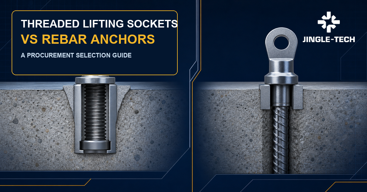
Threaded Lifting Sockets vs Rebar Anchors: A Precast Buyer's Selection and RFQ Guide
Quick answer: “threaded lifting socket” and “rebar anchor” do not always describe two mutually exclusive products. The first name usually describes the connection interface presented at the concrete surface; the second often describes how force is transferred from a socket body into the precast element through an integral or attached reinforcing-bar tail. A product can therefore be both. Buyers should compare complete, approved lifting insert systems by intended lifting stages, element geometry, concrete and reinforcement conditions, load direction, compatible lifting accessory, installation method, traceability and project-specific evidence—not by catalogue family name alone.
A search for threaded lifting socket vs rebar anchor often starts after a drawing review, supplier change or cost comparison. The bill of material may say “lifting socket,” while a competing catalogue says “rebar anchor,” “wavy-tail insert,” “foot anchor,” or another trade name. If purchasing treats those nouns as complete specifications, quotations can conceal different load paths, accessories, installation controls and evidence packages. The lowest line price may not represent the same technical solution.
This guide gives engineering buyers a disciplined way to frame the decision. It separates temporary lifting inserts from permanent structural anchors and ordinary reinforcement.It also keeps the cast-in insert distinct from the detachable item connected to the crane or hoist. That boundary matters because different standards, legal duties, inspection practices and responsible parties may apply to the insert, lifting accessory, precast element and lifting operation.
If you already have a released element drawing, planned lift stages, quantities and an approved system basis, Discuss a controlled lifting-insert RFQ. A useful commercial review can flag missing inputs and quotation differences; it cannot replace the project engineer's selection or the competent person's lift approval.
1. Define the terms before comparing products
For this article, a threaded lifting socket means a cast-in insert assembly that presents an internal threaded interface for a compatible temporary lifting accessory. The embedded body may transfer force through a shaped foot, a plate, a cross feature, a forged tail, reinforcement provided by the element designer, an attached bar, or another validated system geometry. The visible thread is only one part of the load path.
A rebar anchor means a cast-in temporary lifting insert whose load-transfer arrangement includes a ribbed reinforcing-bar tail or a product sold under a rebar-tail, foot or similar family description.In many systems it still ends in an internally threaded socket at the element surface. It does not mean a post-installed reinforcing bar, a reinforcing-bar anchorage used for permanent structural action, or a generic bar that a buyer may weld or bend onto a socket without system authorization.
Those working definitions expose the main sourcing trap: one term describes the upper interface and the other can describe the lower anchorage form. A catalogue comparison must therefore start with drawings and system documents. Ask each bidder to identify the exact insert body, embedded tail or foot, recess former, closure, compatible lifting accessory, required supplementary reinforcement, installation orientation, identification method and permitted use conditions. Without that system map, a “versus” table can compare a thread on one side with a load-transfer detail on the other.
| Question | Threaded lifting socket label | Rebar-anchor label | Buyer action |
|---|---|---|---|
| Surface interface | Usually indicates an internal thread for a matching lifting accessory. | May also use an internal thread; the family name may not describe it. | Record the exact thread, accessory, engagement and system compatibility. |
| Embedded load transfer | Not established by the word “socket.” | Usually implies a ribbed bar or tail, but geometry and joining route still vary. | Compare the controlled assembly drawing and validated system data. |
| Element suitability | Not proven by thread size or socket length. | Not proven by bar diameter, shape or apparent embedment. | Have the engineer check element geometry, reinforcement, concrete, edges and every lift stage. |
| Interchangeability | A matching nominal thread does not establish an approved combination. | A similar bar tail does not establish equivalent system performance. | Require written compatibility and deviation review for the complete system. |
| Commercial comparison | Price may exclude formers, closures, lifting accessories or documents. | Price may hide a different bar grade, joining route or installation burden. | Normalize scope, evidence, tooling, accessories, packaging and buyer approvals. |
2.Set the standards boundary before the product discussion
Temporary lifting inserts sit at the intersection of precast design, lifting-system product requirements, workplace safety and project specifications. No single public catalogue page resolves all of those layers. The buyer should first identify the country of manufacture, destination, project code, contractual standard editions and the party authorized to approve the system.
PD CEN/TR 15728:2016, which BSI lists as the current release, addresses the design and use of inserts for lifting and handling precast concrete elements. DIN Media's official summary of DIN CEN/TR 15728:2017-10 emphasizes that lifting and moving should be included in precast-product design, that failure may endanger life or cause major economic consequences, and that qualified personnel should select and install inserts using instructions for installation and use. Its scope is a valuable boundary: cast-in inserts used during transient lifting and handling are not automatically permanent structural anchors.
VDI/BV-BS 6205:2021-09 is titled “Lifting inserts and lifting systems for precast concrete elements.” DIN Media lists the 2021 edition as current and describes a safety concept spanning development, manufacture, testing, monitoring, planning and use. That breadth is a reminder that a component drawing alone is not the entire system file.
BSI lists BS EN 13155:2020+A1:2025 incorporating corrigendum AC:2026 as the current publication for crane safety and non-fixed load lifting attachments, including lifting insert systems for use in normal-weight concrete within its scope. Its requirements do not authorize an arbitrary mix of socket, tail, attachment and element. Use the complete licensed standard and the project-adopted route to determine which clauses and conformity duties apply.
Regulatory duties differ by jurisdiction. In the United States, OSHA 29 CFR 1926.704 contains specific requirements for precast-concrete lifting inserts, lifting hardware and people beneath precast members. It is a US construction rule, not a global design formula and not a substitute for product-system evidence. In the United Kingdom, HSE's LOLER overview stresses suitable equipment, marking, competent planning, supervision and examination within its legal scope.Buyers should route legal applicability to competent project advisers rather than converting a foreign rule into a universal procurement number.
3. Start with the element and every handling stage
A lifting insert is selected for a sequence, not for a catalogue photograph. The element may be stripped from a mould, rotated, moved within a plant, stored, loaded for transport, unloaded, tilted, erected and then removed from temporary handling service. The governing direction, dynamic condition, rigging geometry, support condition, concrete maturity and consequence of failure can change from one stage to the next.
Procurement should ask engineering for a lift-stage schedule before requesting alternatives. That schedule need not expose proprietary calculations to every bidder. It should, however, define the information a system supplier needs: element identity and revision, mass properties approved by engineering, lifting-point arrangement, planned sequence, orientation at each stage, rigging concept, permitted load directions, whether rotation occurs, expected use environment, concrete condition at each lift, relevant edge or opening geometry and any collision or access constraints.
Do not assume the final erection lift controls. A mould-stripping stage may impose adhesion effects or a direction different from the final pick. Rotation can change the share carried by each point. Unequal sling geometry, tolerances in point position, crane motion, impact and handling practices may affect the design actions.The responsible engineer and lift planner must determine which effects apply and how they are combined. The RFQ should transmit the resulting approved design requirements—not ask a supplier to guess them from the element's total mass.
The minimum element information pack
- Released element drawing and revision, including openings, recesses, edges, thickness changes, reinforcement zones and insert coordinates.
- Approved handling sequence and orientation, with each lift stage clearly named rather than bundled under “normal lifting.”
- Engineering-defined actions and directions at each insert, including any conditions that make the demand asymmetric.
- Concrete specification and the project-defined condition required at each lift, with the verification and release owner identified.
- Reinforcement arrangement around the insert, including congestion, cover and any supplementary reinforcement controlled by the design.
- Rigging and access envelope: lifting accessory, recess clearance, sling or chain approach, rotation and removal needs.
- Exposure, storage and surface requirements before, during and after handling.
4. Compare complete system architecture, not isolated steel parts
The insert, recess former, closure, lifting accessory and element reinforcement form an interface chain.A bidder should state whether it is quoting a complete family, a drawing-controlled insert that must work inside an already approved family, or only a metal component. Those are different scopes with different engineering and liability implications.
For a threaded system, the surface interface creates several control points: thread form and pitch, tolerance, effective engagement, bottoming clearance, recess geometry, contamination protection, accessory seating and any rule on rotation or side loading. A nominal “M” designation identifies a metric thread family, not a lifting-system approval. ISO's current catalogues show ISO 261:1998 for the general plan, ISO 965-1:2026 for tolerance principles and basic data, ISO 965-2:2024 for stated limits and classes, and ISO 1502:1996 for gauges and gauging. These documents can support a drawing when their scopes fit; none proves that a lifting accessory and insert are an approved combination.
For a rebar-tail assembly, the embedded architecture introduces its own controls: bar specification and condition, rib geometry, tail shape, connection to the socket body, orientation, bend or end form, supplementary reinforcement and the space needed to place and compact concrete.An apparently longer or heavier tail is not automatically better. It may conflict with reinforcement, an opening, a thin zone or the intended load-transfer mechanism.
5. Use a selection matrix that exposes engineering decisions
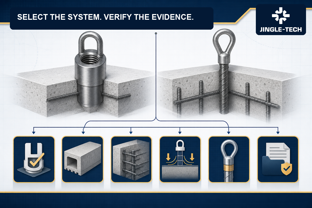
A threaded lifting socket vs rebar anchor decision matrix helps teams ask the same questions of both options without pretending the answer is universal. “Potential advantage” should never be translated into “approved for this element” until the project engineer has checked the system data and design basis. The table below is therefore a question generator, not a rating chart.
| Consideration | Questions for a socket-led concept | Questions for a rebar-tail concept |
|---|---|---|
| Available depth and local thickness | What embedded feature transfers force, and does the validated detail fit the local section? | Can the tail fit without unapproved cutting, bending or interference? |
| Reinforcement congestion | Can the insert and required reinforcement be placed, fixed and concreted as designed? | Can the bar tail be oriented and tied while preserving approved cover and cage geometry? |
| Load direction and rotation | Does the system document permit the planned direction and accessory movement? | How must the tail align with the designed force path,and what directions are permitted? |
| Accessory control | How are the exact mating thread, seating and condition verified before use? | If the top is threaded, the same compatibility questions apply; if not, what proprietary interface controls the connection? |
| Joining route | Is the body one piece, mechanically assembled or welded, and what evidence controls that route? | How is the bar joined to the socket, and is any weld within a qualified and applicable route? |
| Factory installation | What former, cap, fixing and orientation checks prevent movement or contamination? | What tail orientation, cage attachment and concrete-placement controls are required? |
| Traceability | Can the socket body, thread inspection, material and lot marking be linked to shipment? | Can the bar material, joining record,assembly inspection and lot identity remain linked? |
| Future access | Can the recess be protected, cleaned and closed as the project requires? | Does the same surface-interface requirement apply, and how is the embedded tail documented after casting? |
When both concepts remain technically viable, send the matrix, element inputs and required evidence to bidders in the same format. Request a comparable insert-system review. Keep all preliminary supplier proposals marked “not approved” until the authorized engineering process is complete.
6. Treat concrete, edges and reinforcement as part of the system
The steel component is only half the anchorage. The concrete surrounding the insert and the element's reinforcement provide the medium through which action reaches the wider member. Local thickness, edge proximity, openings, voids, ducts, prestressing tendons, reinforcement congestion, cover, casting direction, compaction and concrete condition can change the suitability of a detail.
Procurement should never negotiate an insert substitution without an element-level review.A proposal may preserve the nominal thread yet alter the embedded body, tail orientation, required supplementary reinforcement or recess. That change can affect cage detailing, mould fixtures, placement sequence, concrete flow, drawing coordination and inspection. A substitution request should therefore include a controlled comparison drawing, system-document references, explicit differences and the supplier's evidence—not merely a statement that two items have the same capacity label.
Concrete verification also needs a named owner. The system instructions and project design may condition lifting on an achieved concrete property or other release criterion. The precast producer should define how that condition is measured, recorded and linked to the element before the lift is released. A calendar age or visual impression should not silently replace the approved criterion.
Prestressed elements add another coordination layer. HSE's official page on pre-stressed concrete notes that units should be handled according to the designer's instructions and lifted as intended. For purchasing, the lesson is direct: do not relocate or reorient an insert to simplify a cage or mould without the responsible designer's approval.
7. Review load direction, rotation and accessory movement
A vertical icon in a catalogue can create false confidence.Real handling may include oblique sling legs, tilting, rotation, changing support points, unequal sharing and short periods in which the accessory approaches the recess at an angle. The system's permitted directions, reduction rules, accessory articulation and installation orientation must match the approved lift plan. They cannot be inferred from the shape of an eye or from the apparent robustness of a bar tail.
The engineer should identify the direction of action relative to the insert and embedded tail at every relevant stage. A rebar-tail concept may depend on a controlled orientation relative to that direction. A socket-led concept with another embedded feature may have its own orientation or edge constraints. If a lifting accessory must swivel, rotate or seat in a recess, the accessible envelope must be checked against the concrete surface, chamfers, adjacent inserts, reinforcement and rigging.
Ask bidders to return annotated system drawings showing the permitted connection, direction and accessory movement for the proposed item. A generic statement such as “suitable for angled lifting” is not enough. The response should cite the exact product document and edition, identify any limitations, and state which input remains for project engineering. If a bidder's statement conflicts with the licensed standard, system instructions or element design, stop the comparison and resolve the discrepancy through formal technical review.
8.Control the threaded interface as a safety-critical pairing
The convenience of a threaded connection is also its main purchasing risk: components from different sources can appear to fit. Physical engagement does not prove system compatibility, material suitability, complete seating, rated performance or acceptable condition. Even within one nominal size, thread form, pitch, tolerance, coating, wear, dirt, concrete slurry, corrosion or bottoming can change the connection.
The controlled bill of material should name the exact insert and mating accessory, not merely a nominal thread. The receiving plan should distinguish the reusable lifting accessory from the cast-in insert and should preserve identification for both. The work instruction should define cleaning, visual checks, rejection criteria, engagement confirmation, seating and any prohibition on improvised tools or extensions. Those requirements must come from the approved system and competent lift process.
Thread gauging is one element of product verification, not a field approval test. ISO 1502:1996 describes gauges for checking ISO general-purpose metric screw threads, while ISO 965-1:2026 and ISO 965-2:2024 define particular tolerance frameworks and limits within their scopes. A procurement specification should state whether those references actually apply to the proposed lifting interface, when the thread is inspected, how coatings are treated, which gauges are used and how the result is recorded. If the system uses a proprietary or differently controlled thread, the drawing and authorized method must say so.
Thread-interface questions for an RFQ
- What exact insert and lifting accessory combination is proposed, and where is that compatibility authorized?
- Which thread designation, tolerance and inspection method control the manufactured parts?
- How are effective engagement, seating, clearance and recess geometry addressed in the system instructions?
- How is the internal thread protected during storage, cage assembly, casting, finishing and transport?
- What inspection differentiates harmless appearance variation from damage, contamination or corrosion that requires rejection?
- How are reusable accessories identified, examined, quarantined and retired under the applicable workplace system?
9. If a rebar tail is joined to a socket, make the joining route visible
A rebar-tail assembly may be forged, mechanically connected, friction joined, welded or produced by another controlled route. Procurement should not assume a weld exists, and it should not assume that any visible weld is acceptable. The supplier's controlled drawing and process route should state how the load path passes from socket body to tail and which characteristics are critical.
Where a load-bearing weld to reinforcing steel is part of the approved design, the applicable welding standard, material weldability, joint design, procedure qualification, personnel qualification, production controls, inspection and acceptance must be defined.ISO lists ISO 17660-1:2006 as published but due for revision. Its scope includes load-bearing welded joints between reinforcing bars and other steel components, including connection devices and insert anchors, for the conditions stated in the standard. A 2026 draft revision exists, but a draft is not the published replacement. The contract should cite the edition actually adopted and verify that its scope fits the joint and loading.
The bar itself also needs a controlled specification. ISO 6935-2:2019 specifies technical requirements for ribbed reinforcing bars within its scope and distinguishes weldable from non-weldable steels. ISO 15630-1:2019, confirmed current by ISO in 2024, addresses test methods for reinforcing bars, rods and wire. These standards do not automatically govern every regional bar grade or lifting insert; they show why “rebar” is not a complete material callout.
Ask for the exact bar designation and condition, source and certificate linkage, join type, process specification, production record, inspection method and lot definition. If bending or shaping occurs, the drawing should control it and the approved process should consider the selected material and any joining sequence.Never request an unreviewed bend, weld repair or tail shortening to solve a cage-fit problem on the shop floor.
10. Evaluate installation practicality without letting it override design
A technically valid insert can still fail as a production choice if the plant cannot place, secure, inspect and cast it consistently. Conversely, an easy-to-fix insert is not acceptable if its load path is unsuitable. The installation review should therefore happen early and feed facts back to engineering rather than turning production convenience into an uncontrolled substitution.
For each option, walk through the mould and cage sequence. Identify how the insert is fixed to the form, how its orientation is controlled, what prevents displacement, how the recess is formed, how the internal interface is protected, how concrete can flow and compact around the embedded feature, and how the location is verified before and after casting. Check whether workers can see the identification mark and whether inspection remains possible after reinforcement is closed.
A long or bent bar tail may compete with main reinforcement, ties, ducts or prestressing components. A compact socket body may reduce one interference yet require a separate local reinforcement detail or a different recess. Those are project-specific tradeoffs. The review should produce marked-up drawings, photographs or a controlled trial record only when the buyer's process permits them.Any trial is not evidence of lifting approval unless the authorized engineering and quality plan explicitly make it part of the validation route.
Pre-pour hold points worth defining
- Correct product family, exact part identity, lot and drawing revision.
- Approved coordinates, depth, orientation, recess former and mould attachment.
- Required supplementary reinforcement present and placed to the released detail.
- No unapproved interference, cutting, welding, bending or substitution.
- Socket opening protected and the interface free from damage or contamination.
- Inspection result recorded against the element identity before the pour is released.
11. Specify material and finish as functional requirements
“Steel socket” and “rebar tail” do not define grade, condition, weldability, toughness, heat treatment, surface, corrosion behavior or traceability. The drawing or system specification should identify the accepted material route and prohibited substitutions. The supplier should return the exact offered grade, certificate basis and any difference from the inquiry.
Surface selection should reflect the entire lifecycle: manufacturing, storage, casting environment, stripping, transport, site exposure and the required appearance or closure after use. A coating may affect thread fit, gauge practice, seating, weldability or identification.Stainless material may change joining and galling considerations. Mixed materials can introduce additional corrosion questions. There is no universal “best finish”; the project should define the environment and approved system route.
For a cast-in temporary lifting insert, visible corrosion after storage may be more than a cosmetic question, but procurement should not invent a pass/fail rule. Obtain the approved manufacturer's storage, cleaning and rejection instructions and integrate them with project quality controls. If the condition is outside those instructions or its effect is uncertain, quarantine the item and seek a documented disposition from the authorized parties.
12. Ask for evidence that follows the actual failure paths
A certificate can be genuine and still be irrelevant. The evidence plan should connect each critical characteristic to a reason, method, frequency, acceptance basis, record and lot. For a threaded socket system, that chain may include material identity, body geometry, thread, embedded feature, joining route, surface, marking and packaging. A rebar-tail assembly adds bar material, tail geometry and joint controls. The concrete anchorage and lifting performance remain system-and-element questions, not conclusions that can be drawn from a metal certificate alone.
Do not ask every supplier for the same generic stack of paperwork. Start with the governing system and project documents, then identify what the supplier must provide and what the precast producer must record.Some evidence belongs at product qualification, some at process approval, some at each production lot, some at first article and some at installation or element release. Mixing those levels creates cost without necessarily increasing confidence.
| Evidence layer | Question it should answer | Possible controlled record | Common weakness |
|---|---|---|---|
| System basis | What exact combination is validated, for what scope and under which document edition? | System technical file, instructions, declared scope and approved project review. | A brochure is treated as a complete engineering approval. |
| Material | What metal entered the socket, tail and any joined components? | Certificate linkage, receiving record and controlled material identity. | A certificate cannot be linked to the shipped lot. |
| Manufacturing route | Were critical forming, machining, joining and finishing steps controlled? | Route card, approved procedure, operator or equipment record, outside-process linkage. | Outsourced steps disappear from the lot history. |
| Product inspection | Do geometry, thread, joint, surface and marking meet the controlled requirement? | Inspection plan, calibrated method, first-piece and final lot records. | A report lists “pass” without requirement, method or sample identity. |
| Precast installation | Was the approved insert installed in the approved element detail? | Pre-pour checklist, element/lot link, concrete release record and nonconformance disposition. | Insert paperwork is complete, but the element-level link is missing. |
| Use and examination | Was the compatible accessory in acceptable condition and the lift properly controlled? | Accessory identity/examination, lift plan, pre-use checks and competent release. | A product certificate is mistaken for permission to perform the lift. |
13. Build lot traceability from steel to precast element
Traceability should answer a practical question: if one insert, material heat, joining batch, inspection record or accessory is questioned, which products and elements are affected? A useful map links raw material and critical process records to the insert lot; the insert lot to labeled packs and shipment; and the precast producer's receiving and installation records to individual elements or a controlled element batch.
The lot definition should be agreed before orders start. It may depend on material, process, equipment, time window, inspection group or other factors defined by the applicable quality plan. Procurement should not choose a lot size from convenience alone. Quality and engineering should identify which changes break the lot and which records must follow it.
Marking must remain legible and meaningful without weakening the component or confusing field users. If individual marking is restricted by geometry, the approved system may rely on color, package identity, tags or another method; the project should assess the risk of separation from the package. Avoid colors or marks that can be misread as a capacity or approval category unless the system documents define them.
A shipment record should show the buyer part number, supplier part identity, revision or standard edition, quantity, lot, manufacturing or supply source as contractually required, relevant certificates, inspection release and package mapping. The precast plant can then record which lot went into which element. That chain is far more useful than a generic certificate stored under the purchase-order number with no item-level link.
14. Compare quotations on one normalized scope
Two technically different lifting systems can generate deceptively similar unit prices. One quote may include the insert, closure, former, compatible lifting accessory, controlled drawing, inspection record and protective packaging. Another may include only the cast-in steel body.A third may assume that the buyer supplies or reuses accessories from an existing family. Before comparing totals, convert every offer to a common scope.
Separate recurring piece price from one-time engineering, tooling, gauges, samples, qualification work and freight. Ask how minimum manufacturing batch, release quantity and packaging quantity differ. A rebar-tail assembly may have material and joining cost drivers that a compact socket body does not; a different socket concept may require system-specific accessories or mould hardware. Neither pattern proves which option has lower total cost for the project.
Schedule should be broken into decision gates. Technical review, buyer approval, tooling or gauges, material, forming or machining, joining, finishing, inspection, document release, packaging and transport may each carry a different dependency. Ask the bidder which dates are estimates and which become commitments only after drawings, samples or documents are approved. Do not advertise or plan around a universal lead time.
| Cost or scope block | Buyer baseline | Supplier return | Comparison check |
|---|---|---|---|
| Insert assembly | Exact drawing/system revision and quantity by release. | Included body, tail/foot, closure and marking; explicit deviations. | Are both bidders pricing the same technical boundary? |
| Reusable accessories | Approved type, planned quantity, examination and replacement responsibility. | Included/excluded items, compatibility evidence and user instructions. | Has the comparison counted the whole fleet and its control? |
| Mould and installation items | Former, fixing, cap, gauge and replacement assumptions. | Unit price, life/use assumptions where approved, and availability. | Will changing system create hidden plant conversion cost? |
| Technical and quality evidence | Required review, sample, inspection and document package. | One-time and recurring charges, source and delivery timing. | Are exclusions or proprietary evidence gaps visible? |
| Packaging and logistics | Lot segregation, labels, corrosion protection, destination and Incoterm. | Pack quantity, pallet plan, storage limits, freight basis and exclusions. | Will the package preserve identity and condition at point of use? |
| Change and contingency | Notification rules, approved alternatives and continuity plan. | Controlled source/process list and proposed response to interruption. | Does resilience depend on an unapproved substitute? |
15. Use hypothetical scenarios to test the decision logic
Hypothetical scenario A: a thin architectural element with a congested cage
A buyer receives a request to reduce visible recess work on an architectural element. The first proposal uses a threaded socket with a compact embedded feature and system-defined local reinforcement. A second proposal uses a socket connected to a ribbed bar tail. The team initially favors the second because the bar looks familiar to the precast plant.
The selection matrix changes the discussion. The bar tail crosses a congested zone and would require an unapproved change in orientation. The compact alternative fits more easily but needs a reinforcement detail the buyer has not yet incorporated. Neither can be ordered from the concept sketch. Engineering asks both suppliers for controlled system drawings, permitted directions, recess/accessory details and evidence. Production checks mould fixing and concrete placement. Quality defines pre-pour records. Commercial comparison waits until both proposals reach the same approved scope.
The lesson is not that compact always beats rebar-tail. It is that cage familiarity is not approval, and a shorter insert is not automatically suitable for a thin element. The final decision belongs to the design and lift process using the complete evidence.
Hypothetical scenario B: a robust unit with several rotations
Another hypothetical project involves a precast unit handled in multiple orientations before erection. Both proposed systems fit the local section. The first offer uses an internally threaded body with one embedded load-transfer arrangement; the second uses a threaded socket with an integral rebar tail. Unit prices are close.
The decisive questions concern the sequence. The approved lift plan produces different directions at different stages, and the lifting accessory must move without bearing incorrectly on the recess. Engineering checks the permitted system directions and point arrangement. The plant confirms tail or insert orientation can be held during casting.Purchasing includes the exact compatible accessory fleet, closures and formers in both quotes. Quality links accessory examination and insert lots to the job.
Again, there is no universal winner. A rebar-tail option may align well with one approved load path, while another system architecture may suit the full sequence better. The useful output is a documented decision that remains valid from mould to site—not a catalogue preference detached from the lift stages.
16. Draft an RFQ that suppliers can answer without guessing
A high-conversion inquiry is not a one-line request for “best price.” It gives enough controlled information for a supplier to expose technical and commercial differences. Where data are not final, label them as open and identify who will close them. This is more credible than letting each bidder invent a different assumption.
| RFQ block | Information to send | Return required from bidder |
|---|---|---|
| Project boundary | Destination, applicable regulatory route, adopted standards/editions, intended temporary handling scope. | Applicable proposed system documents, scope statement and unresolved compliance questions. |
| Element and lift | Released drawing, geometry, reinforcement context, engineering actions/directions and named lift stages. | Exact proposed insert/system, required inputs, limits and annotated arrangement—subject to buyer approval. |
| Component definition | Drawing/system identity, material, surface, thread/interface, recess, accessory, closure and supplementary reinforcement boundary. | Compliance matrix, controlled drawing, material/process route and every deviation. |
| Quality evidence | Required qualification basis, inspections, methods, frequency, certificates, traceability and record language/format. | Sample evidence pack, inspection plan, lot definition and subcontract-process controls. |
| Demand and release | Annual forecast if available, firm quantity, release pattern, sample/pilot need and required dates. | Minimum batch assumptions, price breaks, capacity reservation assumptions and gate-based schedule. |
| Packaging and delivery | Label fields, lot segregation, corrosion/contamination protection, pack quantities, destination and Incoterm. | Proposed packaging, sample labels, pallet data, storage instructions, freight basis and exclusions. |
| Approval and change | Authorized approvers, deviation form, no-change rules, notification period and document retention. | Signed acknowledgement, change-control process and list of controlled outside sources. |
For faster review, attach a one-page compliance matrix with rows for every requirement and columns for “comply,” “deviation,” “evidence reference,” “buyer decision” and “closed by/date.” Do not accept blank cells as compliance. A bidder may legitimately need more element data; recording that question is safer than a confident but unsupported answer.
17. Audit the supply route without inventing capability claims
A responsible buyer verifies the proposed route rather than assuming that a website headline proves it. Ask one supplier to walk a representative item through technical review, material control, forming or machining, tail preparation, joining if applicable, finishing, inspection, marking and packaging. For every outside process, identify the approved source, transfer document, incoming verification and lot-link method.
Useful audit evidence can be redacted.A route card, drawing-review checklist, material link, first-piece report, gauge record, special-process record, final inspection, label and nonconformance example can show how the system works without exposing unrelated customer information. Follow one part and lot across the records. A polished manual with no transaction-level link is less persuasive than a small coherent trail.
Ask who has authority to stop production, approve a deviation, release a lot and notify the buyer of change. Confirm how obsolete drawings and system instructions are withdrawn. Review calibration and maintenance only for equipment used to verify the contracted characteristics. If testing or qualification is performed externally, include the laboratory or source, method, sample identity and report linkage in the same control chain.
This guide makes no claim that JINGLE-TECH holds a particular certification, operates a particular factory or laboratory, or has completed a particular customer program. Those statements require current, reviewable evidence for the exact legal entity and supply route. Buyers should request that evidence directly and evaluate it against their own approval procedure.
18. Connect this decision to the wider sourcing architecture
A lifting insert may sit inside a much larger procurement program. Use internal links to keep each decision in its own technical lane. For a deeper explanation of the category, see the existing guides on what buyers should know about threaded lifting sockets, lifting sockets for precast projects, and rebar-foot anchor types and uses. Those pages complement this comparison; none replaces project approval.
When the same supplier program includes drawing-controlled hardware, a custom fastener manufacturer review can help define drawing control and evidence. Screw-focused sourcing belongs in the custom screw manufacturer cluster, while building-bolting questions should be routed to the structural bolt manufacturer guide. Those product families are not temporary precast lifting inserts.
Likewise, a concrete anchor manufacturer page generally addresses another anchoring context, and the custom nut manufacturer guide focuses on threaded joint components. A hose clamp manufacturer evaluation uses different service and validation questions.Keeping those terms separate prevents broad “metal hardware” sourcing from erasing application-specific duties.
For the temporary lifting system itself, the lifting anchor manufacturer guide explains the wider supplier check, and the precast concrete accessories manufacturer page covers related accessory sourcing. If the program contains machined interfaces, use the precision CNC machining parts manufacturer checklist. Multi-family programs can then be coordinated through the OEM fastener and machined parts supplier framework without implying that one quality plan fits every safety function.
19. Receiving, storage and handover are part of selection
The best insert on paper can be undermined by mixed lots, damaged threads, missing closures or uncontrolled reusable accessories. The receiving plan should compare shipment identity with the purchase order and approved drawing, check pack condition, verify required documents and maintain quarantine until discrepancies are resolved. Sampling must follow the contract and risk plan; it should not be improvised from a generic AQL table for a safety-critical application.
ISO publishes ISO 2859-1:2026 for AQL-indexed lot-by-lot sampling by attributes. That standard can support an agreed inspection system within its scope, but an AQL is not a statement that an individual critical defect is harmless. Engineering and quality should decide which characteristics need process controls, qualification, first-article work, proof or functional evidence, alternative sampling, or full verification. The contract should define the plan, lot and switching rules.
Storage instructions should cover moisture, contamination, mechanical damage, identification and segregation. Threaded openings should remain protected by the approved method. Reusable lifting accessories should be stored and examined under the applicable competent system, separate from unused cast-in inserts. Do not use a field accessory merely because it screws into the socket.
At handover, the site needs the approved lifting plan, element identity, insert-system identity, compatible accessory information, restrictions, examination status and any project-required records. HSE's LOLER guidance highlights competent planning, appropriate supervision and safe execution within UK scope. Other jurisdictions have their own rules. The supplier's shipment release is not the site's authorization to lift.
20. Common specification mistakes and how to correct them
- Mistake: comparing a threaded socket with a rebar tail as if they are exclusive categories. Correct it by drawing the surface interface and embedded load-transfer architecture for each proposed complete system.
- Mistake: ordering by nominal thread and a capacity label. Correct it by naming the exact approved insert/accessory combination, system document, element conditions and lift stages.
- Mistake: treating apparent fit as compatibility. Correct it with written system authorization, controlled drawings and a receiving/use plan that prevents mixing.
- Mistake: asking the supplier to choose reinforcement from element mass alone. Correct it by giving engineering-defined actions, geometry, concrete and cage context and keeping design approval with the responsible engineer.
- Mistake: hiding the join between socket and bar tail. Correct it with a defined material, joint design, qualified process route, inspection and lot evidence where joining is part of the approved system.
- Mistake: changing tail orientation on the shop floor. Correct it by coordinating cage fit before release and processing any change through formal engineering review.
- Mistake: using a foreign regulatory multiplier as a global design rule. Correct it by identifying jurisdiction, applicable law and the complete project/system design basis.
- Mistake: accepting a certificate with no lot link. Correct it by tracing material and process records through insert packs to the precast element.
- Mistake: comparing piece price while excluding accessories and plant conversion. Correct it with a normalized total-scope sheet covering formers, closures, reusable equipment, evidence, packaging and approvals.
- Mistake: describing a hypothetical example as a supplier case. Correct it by labeling teaching scenarios clearly and using verified, permissioned project evidence for real claims.
21. Frequently asked questions
Is a rebar anchor always different from a threaded lifting socket?
No. In supplier terminology, “threaded socket” may describe the connection at the concrete surface, while “rebar anchor” describes an embedded ribbed-bar tail. One product can have both features. Request the complete system drawing and define the terms on the RFQ so bidders quote the same architecture.
Can two inserts with the same nominal thread use the same lifting eye?
Do not assume so. A matching nominal thread does not prove approved compatibility, correct engagement, seating, material, recess geometry or performance. The exact insert and lifting accessory combination must be authorized by the applicable system documents and project approval. Keep incompatible or unverified components segregated.
Which option has the higher lifting capacity?
There is no universal answer.Performance depends on the complete insert system, size and geometry, material, concrete and reinforcement, edge and spacing conditions, direction, lift stage, accessory and other design factors. Compare validated system data for the exact proposal and have the responsible engineer approve the element-specific selection.
Is a longer rebar tail automatically safer?
No. Tail geometry is part of a validated load-transfer arrangement. More length or a different bend can interfere with reinforcement, change the intended mechanism or create installation problems. Never lengthen, shorten, bend or substitute a tail without controlled system and engineering approval.
Can a threaded socket be used as a permanent structural anchor after lifting?
Not merely because it remains in the concrete. This guide concerns temporary lifting and handling inserts. Any permanent structural use requires its own explicit design, applicable standards, durability assessment and approved product basis. A temporary lifting designation does not establish permanent anchorage performance.
May the precast plant weld an ordinary reinforcing bar to a socket?
Only if that exact joint is part of an approved design and controlled route. Material weldability, joint design, procedure, personnel, inspection and applicable standard must be addressed. An improvised weld can change the safety-critical load path and is not an acceptable substitute for a documented system.
What should be included in a threaded lifting socket quotation?
At minimum, identify the exact insert/system, material and surface, thread/interface, compatible accessory, closure and former scope, required local reinforcement boundary, quantities, packaging, technical evidence, inspection records, lot traceability, deviations, commercial assumptions and a gate-based schedule. Keep engineering approval outside the commercial quote.
How should buyers compare threaded lifting socket prices?
Normalize the complete approved system rather than the insert piece alone. Include reusable accessories, formers, closures, mould conversion, gauges, samples, technical review, evidence, inspection, packaging, freight, minimum batches, release quantities and change risk. A lower piece price may represent a narrower scope.
What is the right concrete strength before lifting?
This article intentionally provides no universal value. The required condition depends on the element design, insert system, lifting stage and adopted project requirements. The responsible engineer and approved system documents must define the criterion, while the precast producer's quality process should verify and record it before release.
Can a supplier recommend the insert when the lift plan is incomplete?
A supplier can identify missing inputs and discuss candidate system families, but a preliminary suggestion is not approval. Keep it marked as unapproved until engineering defines the relevant actions, directions, element conditions and lift stages and completes the required review.
What documents should arrive with each lot?
The contract should decide. Depending on the approved plan, the package may include conformity and material linkage, process or joining records, dimensional/thread inspection, product or system evidence references, lot labels, packing list and change/deviation status. Every record should point to the exact part, revision, lot and shipment.
How should a damaged or contaminated socket be handled?
Quarantine it and follow the approved system's inspection and disposition process. Do not force a gauge or accessory, chase the thread, grind the recess, apply an unapproved chemical or make a field repair. The authorized party should determine whether cleaning, further inspection, repair or rejection is permitted.
How often should reusable lifting accessories be examined?
Follow the applicable law, competent examination scheme and system instructions for the jurisdiction and use. Frequency may depend on accessory type, service, condition and legal scope.Do not copy a generic interval from another project, and do not treat an insert certificate as an accessory examination record.
What information produces the fastest qualified supplier response?
Send the released element and insert drawings, named lift stages, engineering-defined actions and directions, concrete and reinforcement context, exact system/accessory boundary, quantities and releases, required evidence, packaging, destination and open questions. A compliance matrix usually saves more time than an urgent one-line request.
22. Official references and edition-control checklist
Editorial status check: 24 August 2026. The official pages below were reviewed for their published title, edition and scope/status on that date. Catalogue summaries are navigational aids; they do not replace licensed standards, legislation, system instructions, released drawings or competent engineering judgment. Recheck status when the contract is formed and after any change.
- BSI: PD CEN/TR 15728:2016—current BSI release for design and use of inserts for lifting and handling precast concrete elements.
- DIN Media: DIN CEN/TR 15728:2017-10—current German publication of CEN/TR 15728:2016; the official summary emphasizes product-design integration, adequate reliability and qualified selection/installation.
- VDI/BV-BS 6205:2021-09—lifting inserts and lifting systems for precast concrete elements.
- BSI's live record includes the 2026 corrigendum: BS EN 13155:2020+A1:2025 incorporating corrigendum AC:2026. The publication is identical to EN 13155:2020+A1:2025/AC:2026 and, within its stated boundaries, covers crane safety and non-fixed load lifting attachments, including lifting insert systems used in normal-weight concrete.
- For work in the United States, read OSHA 29 CFR 1926.704 on OSHA's own site. It is a US construction rule for precast operations, not a worldwide product-design standard.
- HSE: LOLER overview—UK guidance on lifting-equipment suitability, marking, planning, supervision and thorough examination within legal scope.
- HSE: Pre-stressed concrete—official handling reminder that units should be lifted as intended by the designer.
- ISO 261:1998—general plan for ISO general-purpose metric screw threads; ISO confirmed it in 2024.
- ISO 965-1:2026—tolerance-system principles and basic data for ISO general-purpose metric screw threads within scope.
- ISO 965-2:2024—limits for the thread classes and size ranges stated in its scope.
- ISO 1502:1996—gauges and gauging for ISO general-purpose metric screw threads; ISO shows systematic review activity, so recheck future status.
- ISO 17660-1:2006—published standard for load-bearing welded joints involving reinforcing steel within stated scope; ISO lists it for revision, and a draft replacement is not yet the published standard.
- ISO 6935-2:2019—technical requirements for ribbed reinforcing bars within its scope; ISO lists it under review.
- ISO 15630-1:2019—test methods for reinforcing bars, rods and wire; confirmed current by ISO in 2024.
- ISO 2859-1:2026—AQL-indexed lot-by-lot sampling schemes by attributes; use only as part of an approved inspection strategy.
Put the exact adopted edition on the purchase order and supplier acknowledgement. “Latest edition” can shift a technical decision to an uncontrolled date; an old edition can silently preserve superseded requirements. Where a standard is under review or revision, record that status without treating a draft as the governing publication. Evaluate changes through the buyer's formal design and contract process.
23. Turn the comparison into a qualified inquiry
The best result of a threaded lifting socket vs rebar anchor review is not a generic winner.It is a controlled shortlist in which every option is tied to the same element, lift stages, approved actions, compatible accessories, installation boundary, evidence and commercial scope. That makes engineering review faster and prevents purchasing from comparing unlike products.
Send a useful first package: element drawing and revision, planned handling sequence, engineering-defined insert actions and directions, concrete and reinforcement context, preferred or existing system interface, quantities and release pattern, destination, documentation requirements and unresolved questions. Ask the bidder to return an annotated proposal and compliance matrix. Keep every recommendation preliminary until your authorized engineer and competent lifting team complete their reviews.