How to Specify Precast Concrete Insert Plates with Welded Studs

Precast concrete insert plates provide a prepared steel connection point at the surface of a concrete element. A typical assembly combines a steel plate with welded headed studs or other anchors that are cast into the concrete. After demolding, the exposed plate can be used for a welded or bolted connection defined by the project design.
Choosing an insert plate by length and width alone is not enough. A complete specification must connect the structural design, plate material, stud geometry, weld requirements, reinforcement layout, corrosion environment, formwork method, inspection plan, and installation sequence.
If one of these inputs is missing, a component that looks acceptable on the factory floor may still create a fit-up, durability, traceability, or installation problem on site.
This guide explains how engineers and procurement teams can evaluate precast concrete insert plates before requesting a quotation or approving production. It is a purchasing and manufacturing guide—not a substitute for connection design by the responsible engineer.
Quick Answer: What Should an Insert Plate Specification Include?
A workable request for quotation should define at least the following:
-
Approved drawing number and revision
-
Plate dimensions, thickness, edge condition, and material grade
-
Stud type, diameter, length, quantity, location, and orientation
-
Weld process, qualification, inspection, and acceptance requirements
-
Surface condition or coating system
-
Concrete strength and relevant exposure conditions
-
Required concrete cover, edge distance, and reinforcement clearance
-
Plate-face position and allowable installation tolerance
-
Quantity, packaging, traceability, and documentation
-
Project standard, contract specification, and destination market
Do not ask a supplier to infer safety-critical values from a product photograph. Load resistance, weld acceptance, embedment, edge distance, and reinforcement interaction must come from the approved design basis.
1. What Are Precast Concrete Insert Plates?
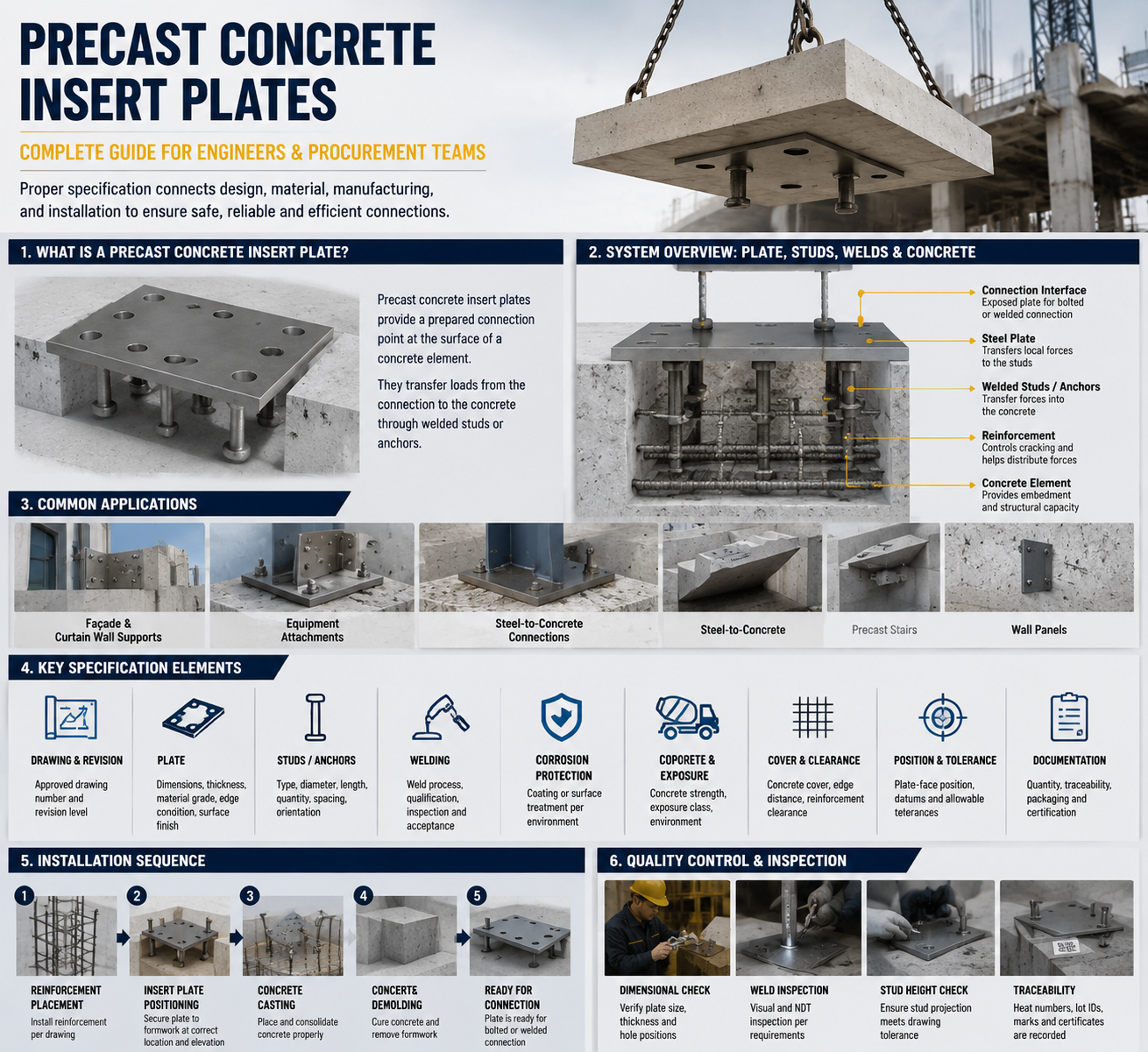
Precast concrete insert plates—also called embed plates, embedded plates, or steel insert plates—are cast-in components used to create a connection interface between concrete and another structural or non-structural element.
Common applications include:
-
Façade and curtain-wall supports
-
Equipment attachments
-
Steel-to-concrete connections
-
Brackets and support frames
-
Precast stairs
-
Wall panels
-
Structural connection assemblies
-
Project-specific welded connections
The exposed steel face makes later connection work more predictable, but the visible plate is only one part of the system.
The anchors behind the plate transfer forces into the concrete. Reinforcement, concrete geometry, edge distance, weld quality, and construction tolerances all influence whether the assembly can perform as intended.
Who specifies or purchases insert plates?
Structural and precast engineers define the connection intent and critical geometry.
Precast factories coordinate the insert with reinforcement, formwork, casting, vibration, and demolding.
Quality engineers control material records, weld inspection, dimensional checks, and traceability.
Project managers manage approvals, drawing revisions, samples, milestones, and delivery risks.
Procurement teams compare quotations, manufacturing capability, documentation, packaging, and total project cost.
When is a catalogue product not enough?
Custom manufacturing is usually required when the project has:
-
Unusual plate dimensions
-
Non-standard stud spacing
-
Special materials
-
Project-specific coatings
-
Restricted reinforcement clearance
-
Critical positional tolerances
-
Special inspection requirements
-
Custom marking or packaging
-
Project-specific documentation requirements
Precast concrete insert plates should not be treated as generic lifting devices, post-installed anchors, or interchangeable hardware unless the relevant design and project documents explicitly establish that use.
2. Treat the Plate, Studs, Welds, and Concrete as One System
An insert plate drawing should be read as a complete load-transfer and installation assembly rather than as several unrelated purchasing lines.
Steel plate
The plate provides the exposed connection surface and transfers local actions to the welded anchors.
The drawing should define:
-
Length and width
-
Plate thickness
-
Material grade
-
Flatness
-
Edge condition
-
Hole or slot pattern
-
Connection face
-
Surface finish
-
Critical datums
-
Permitted tolerances
A thicker plate is not automatically a better plate. Increasing thickness can affect weight, welding, galvanizing, distortion, fit-up, and cost without correcting an unsuitable stud layout.
Welded studs or anchors
The anchors transfer forces from the plate into the surrounding concrete.
Their type, quantity, length, diameter, spacing, and orientation must be consistent with the engineered connection.
Substituting a different stud simply because it is available can change:
-
Weld procedure
-
Embedment geometry
-
Concrete cover
-
Reinforcement interference
-
Edge distance
-
Load-transfer behavior
-
Inspection requirements
Any proposed substitution should be reviewed and approved before production.
Welds
The weld is the transition between the steel plate and each stud.
Visual appearance alone does not prove that a weld is acceptable. A uniform-looking weld can still require supporting procedure and inspection evidence.
The purchase specification should define:
-
Applicable welding process
-
Welding procedure requirements
-
Operator qualification
-
Production controls
-
Inspection method
-
Sampling frequency
-
Acceptance criteria
-
Repair and reinspection procedure
Concrete and reinforcement
The surrounding concrete and reinforcement are part of the connection.
Studs must fit within the designed concrete cover and edge distances while avoiding clashes with:
-
Reinforcing bars
-
Lifting anchors
-
Threaded sockets
-
Cast-in channels
-
Electrical conduits
-
Embedded pipes
-
Openings
-
Other connection plates
Coordination should occur before production, not after the inserts arrive at the precast factory.
3. Specify the Product from the Application Backward
Before discussing price, clarify how and where the insert plate will be used.
| Design input | Questions to resolve | Why it matters |
|---|---|---|
| Connection function | What will be welded or bolted to the exposed plate? | Defines the interface and installation sequence |
| Design actions | Which tension, shear, moment, fatigue, or combined actions are considered? | Controls engineered geometry and verification |
| Concrete element | Wall, beam, slab, stair, façade panel, or foundation component? | Affects thickness, edge distance, and reinforcement |
| Exposure | Interior, outdoor, coastal, industrial, humid, or chemical environment? | Guides material and corrosion-protection decisions |
| Construction method | How will the plate be fixed to the mold during casting? | Influences position, cleanliness, and tolerance |
| Site connection | Field welding, shop welding, bolting, or secondary bracket? | Determines access, finish, and inspection needs |
| Maintenance | Will the connection remain accessible after construction? | Affects durability and documentation requirements |
This application-first approach prevents a common purchasing mistake: requesting a visually similar component without identifying the conditions that made the original design suitable.
4. Define the Material and Surface Finish Clearly
Jinglefix’s product information lists S355J2 and stainless steel as available material options, together with plain, electro-galvanized, and hot-dip-galvanized surface conditions.
These are manufacturing options, not recommendations for every project. The project engineer or contract specification must select the appropriate material and finish.
| Material or finish | Typical reason for consideration | What to confirm |
| Plain structural steel | Controlled interior environment or later project coating | Exact grade, certificate, weldability, temporary rust protection |
| Electro-galvanized steel | Appearance or limited corrosion protection where specified | Coating specification, coverage, thickness, post-weld treatment |
| Hot-dip-galvanized steel | More demanding atmospheric exposure where permitted | Coating standard, drainage, distortion control, repair method |
| Stainless steel | Corrosive exposure or project-specific durability requirement | Exact grade, surface condition, weld process, contamination control |
Using the word “galvanized” alone is not a complete coating specification.
For hot-dip-galvanized fabricated steel, ISO 1461 describes general coating properties and test methods. The purchase order should still define the project-specific requirements.
Also confirm how the finish interacts with later site welding. The exposed connection zone may require:
-
Masking before coating
-
Local coating removal
-
A controlled welding area
-
An approved coating-repair system
-
Additional corrosion protection after installation
These details should be agreed before production.
5. Control Stud Layout and Reinforcement Clearance
Stud layout should be transferred directly from the approved drawing.
The fabrication drawing should show:
-
Drawing datums
-
Center-to-center spacing
-
Distance from plate edges
-
Stud orientation
-
Stud projection
-
Weld location
-
Permitted positional tolerance
Before production release, review the insert model against the reinforcement drawing or building information model.
Pay particular attention to:
-
Stud-to-rebar clearance
-
Concrete cover around anchors
-
Distance to concrete edges
-
Distance to openings
-
Conflicts with lifting systems
-
Conflicts with sockets or channels
-
Access for formwork fixing
-
Access for dimensional inspection
-
Movement during concrete placement
-
Movement caused by vibration
-
Orientation errors on symmetrical parts
A physical sample or first-article assembly is valuable when reinforcement is dense, the concrete element is thin, or the formwork fixing method is unfamiliar.
The purpose is not only to confirm the steel component. It is also to confirm that the insert can be positioned, cast, demolded, and connected as planned.
6. Specify Weld Quality as a Controlled Process
Buyers should evaluate how the supplier controls the complete welding process rather than approving welds from photographs alone.
Recommended questions include:
-
Which welding process and equipment will be used?
-
Is there a qualified procedure for the selected plate and stud materials?
-
How are operators qualified and authorized?
-
How are the plate and stud surfaces prepared?
-
Which welding parameters are monitored?
-
Which production tests are required?
-
What is the inspection sampling plan?
-
What are the acceptance criteria?
-
How are rejected welds identified?
-
How are repaired welds reinspected?
The ISO 3834 series provides a framework for selecting fusion-welding quality requirements.
AWS D1.1 addresses structural steel welding when it is invoked by the applicable project specification or contract.
Neither standard should be claimed automatically. The responsible engineer and contract documents determine the applicable standard, edition, qualifications, and acceptance criteria.
7. Establish an Inspection and Documentation Plan
The quality package should be agreed before the quotation is finalized. Adding inspection or documentation requirements after production can create unexpected cost and schedule disputes.
A practical inspection plan may include
-
Incoming material identification
-
Material certificate review
-
Plate length and width
-
Plate thickness
-
Plate flatness
-
Edge condition
-
Stud type and material
-
Stud diameter and length
-
Stud quantity and position
-
Stud orientation and projection
-
Weld appearance
-
Project-defined weld testing
-
Coating inspection
-
Final dimensional inspection
-
Part marking
-
Batch identification
-
Packaging inspection
Documents buyers may request
-
Approved production drawing
-
Drawing revision record
-
Material certificates
-
Welding procedure records
-
Personnel qualification records
-
First-article inspection report
-
Production dimensional report
-
Weld inspection report
-
Coating report
-
Non-conformance report
-
Corrective-action record
-
Packing list
-
Batch labels
-
Certificate of conformity
The correct documentation package depends on project risk.
A non-structural attachment and a safety-critical structural connection should not automatically receive the same inspection plan.
8. Compare Suppliers by Total Project Risk
The lowest unit price can become expensive if the supplier does not control drawings, fixtures, welding, coating, inspection, or documentation.
| Evaluation area | Strong supplier evidence | Risk if missing |
| Drawing review | Supplier asks about datums, tolerances, welds, finish, and inspection | Incorrect assumptions enter production |
| Manufacturing plan | Defined cutting, machining, welding, coating, and inspection sequence | Inconsistent batches and late changes |
| Fixture control | Repeatable stud-positioning method | Stud-location drift or plate distortion |
| Quality records | Inspection results linked to batch and drawing revision | Difficult acceptance and root-cause analysis |
| Change management | Controlled drawing approval and revision system | Mixed revisions or obsolete parts |
| Packaging | Protection against corrosion, impact, and label loss | Damage or identification errors |
| Engineering support | Clear manufacturability and cost feedback | Slow approvals and avoidable redesign |
Ask suppliers to separate the following items in their quotation:
-
Tooling
-
Samples
-
First-article inspection
-
Production inspection
-
Testing
-
Surface treatment
-
Documentation
-
Packaging
-
Freight assumptions
This makes supplier comparisons more meaningful and reduces hidden scope differences.
9. Use a Controlled OEM/ODM Workflow
A reliable custom manufacturing workflow normally follows these stages.
Step 1: Requirement collection
Send the drawing, material, finish, quantity, application, inspection requirements, packaging needs, and destination.
Step 2: Engineering review
Resolve missing dimensions, manufacturability concerns, weld details, coating effects, and inspection access.
Step 3: Quotation and process planning
Confirm manufacturing processes, tooling, sample timing, testing, documentation, lead time, and commercial terms.
Step 4: Prototype or first article
Verify:
-
Plate dimensions
-
Stud position
-
Stud projection
-
Weld condition
-
Surface finish
-
Formwork fit
-
Reinforcement clearance
-
Marking and traceability
Step 5: Approval and revision lock
Record the approved drawing revision and any accepted deviations.
Step 6: Batch production
Control material batches, fixtures, welding parameters, coating, and in-process dimensions.
Step 7: Final inspection
Complete the agreed dimensional, weld, finish, marking, packaging, and documentation checks.
Step 8: Packaging and delivery
Protect exposed connection faces and coatings, separate batches, and maintain label traceability.
Step 9: Repeat-order control
Reuse the approved revision, fixtures, inspection plan, and lessons learned.
This workflow is particularly important for precast concrete insert plates because an anchor hidden inside hardened concrete cannot be easily corrected after casting.
10. What to Send with Your RFQ
Send a complete project package rather than a product screenshot.
RFQ checklist
-
2D drawing
-
3D model, where available
-
Drawing number and revision
-
Measurement units
-
Applicable project standards
-
Plate material and grade
-
Plate dimensions and thickness
-
Stud material and geometry
-
Stud quantity and layout
-
Weld requirements
-
Inspection requirements
-
Surface finish
-
Protected welding areas
-
Critical tolerances
-
Inspection datums
-
Reinforcement constraints
-
Concrete element information
-
Sample requirements
-
First-article requirements
-
Order quantity
-
Forecast volume
-
Marking and traceability
-
Documentation package
-
Packaging requirements
-
Delivery destination
-
Required schedule
If some design details remain under review, identify them as open items. A transparent list of unresolved questions is safer than allowing the supplier to make silent assumptions.
Frequently Asked Questions
1. What is the difference between an insert plate and an anchor plate?
Terminology varies by region and project. Both terms may describe a steel plate connected to anchors and cast into concrete.
The drawing, connection function, and project specification are more reliable than the product name alone.
2. Can I select an insert plate from load capacity alone?
No.
Load resistance depends on the complete engineered system, including the plate, studs, welds, concrete, reinforcement, edge distance, geometry, and loading condition.
Use the approved design and supporting verification.
3. Which plate material is best?
There is no universal best material.
Selection depends on structural requirements, weldability, exposure, finish, maintenance, material availability, and applicable project standards.
Specify the exact grade rather than only “carbon steel” or “stainless steel.”
4. When should I use hot-dip galvanizing?
Use hot-dip galvanizing when the project’s corrosion strategy requires it and the component geometry, welding sequence, and later connection method are compatible.
Confirm the coating standard, inspection method, distortion control, protected connection areas, and repair procedure.
5. Can the studs be moved to avoid reinforcement?
Not without engineering approval.
Changing stud position can affect load transfer, concrete cover, edge distance, reinforcement interaction, and connection behavior.
Coordinate the reinforcement and insert geometry before approving the fabrication drawing.
6. What welding records should I request?
Request the records required by the applicable specification and project risk level.
These may include:
-
Welding procedure qualifications
-
Operator qualifications
-
Production parameter records
-
Visual inspection records
-
Production test results
-
Repair and reinspection records
7. Is a website certification statement enough for project approval?
No.
Verify the current certificate, issuing organization, certificate scope, validity period, covered manufacturing location, and relevance to the exact product.
A management-system certificate is not automatically a product performance certificate.
8. Should I approve a first article?
First-article approval is advisable for:
-
New designs
-
Critical tolerances
-
Dense reinforcement
-
Unfamiliar coatings
-
New suppliers
-
Safety-critical applications
-
Complex documentation packages
The first article should be inspected against the approved drawing and quality plan.
9. How can plate movement during casting be prevented?
Define a suitable formwork fixing method, orientation control, and pre-pour inspection.
The fixing method must hold the plate and anchors in position during concrete placement and vibration without damaging the component.
10. What information does Jinglefix need for a quotation?
Send the drawing or model, material, stud layout, surface finish, critical tolerances, inspection requirements, quantity, packaging needs, and delivery destination.
Jinglefix can then review manufacturability, sampling, production, quality control, and delivery requirements with your team.
Conclusion: Approve the Complete System
The best procurement decision is not simply a steel plate with the correct outside dimensions.
It is an approved connection component supported by:
-
Controlled drawings
-
Suitable materials
-
Repeatable welding
-
Reinforcement coordination
-
Defined inspection
-
Traceable records
-
Protected packaging
-
Reliable revision management
Jinglefix supports custom steel insert plates from drawing review and sample development through batch manufacturing, inspection, packaging, and global delivery.
To discuss a project, send your latest drawing, target material and finish, quantity, inspection requirements, and delivery destination. The engineering team can review open manufacturing questions before quotation and production.
Technical References
-
Jinglefix—Precast Concrete Insert Steel Welding Fastening Plate with Studs
-
ISO 3834-1:2021—Quality requirements for fusion welding of metallic materials
-
ISO 1461:2022—Hot-dip galvanized coatings on fabricated iron and steel articles
Editorial note: Verify all load capacity, tolerance, service-life, coating, certification, and delivery claims against the final drawing, current certificates, test reports, and project contract before publication or order approval.